Products
Direct-drive linear motors and in-house-built machine tools
Our flagship line is the 1ML and 2ML series of direct-drive linear motors, alongside the "Sculptor S2000" CNC stone-processing machine for 3D milling and engraving of natural and artificial stone.
Flagship product
Linear Motors 1ML / 2ML
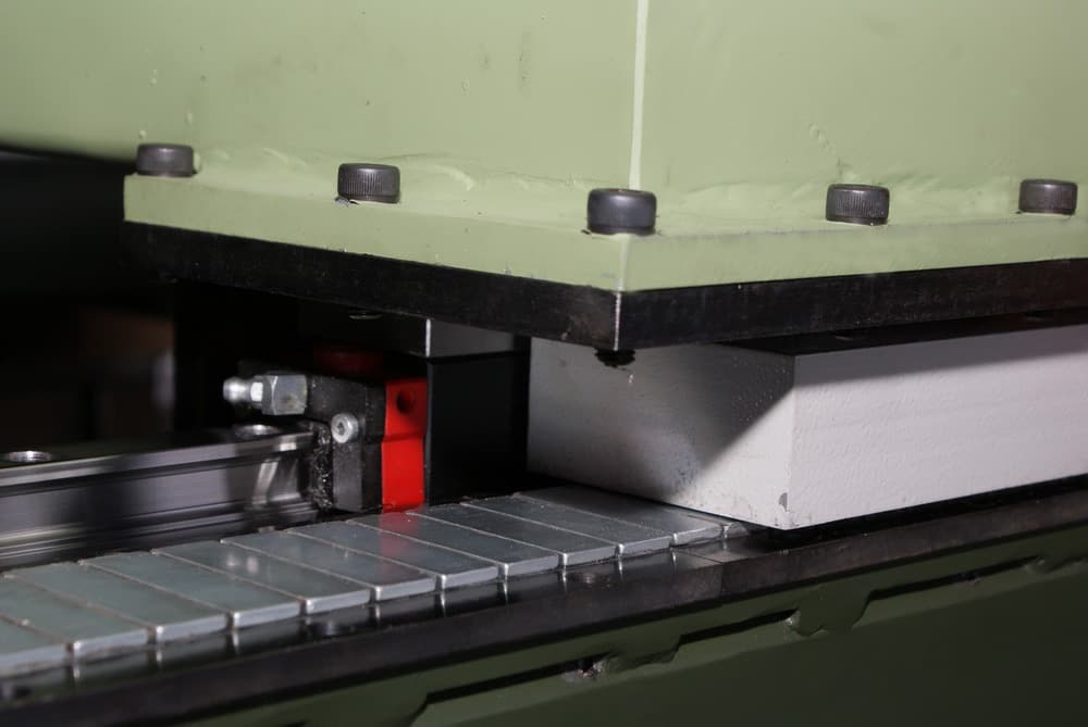
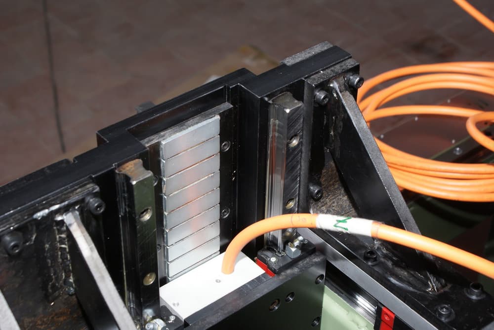
AC synchronous linear motors excited by permanent NdFeB magnets — the foundation of RAO Mars's direct-drive technology. The 1ML series runs on a single-sided magnetic track; the 2ML series uses a symmetric double-sided track with a 0.6 mm air gap. Used in machine building, robotics, transport systems, and multi-axis machining centers.
Technical specifications
Motor parameters and dimensions by frame size
Data from the RAO Mars linear motor catalogue.
The strong attraction between armature and magnetic track makes the series the right choice where bearing preload is needed: preload removes play in the guides. Small dimensions and easy integration into existing designs.
Applications: mechanical engineering, transport and robotic systems, high-dynamics equipment, machine tools, optical inspection and laser cutting systems, packaging machines.
- Magnetic track
- Single-sided
- Sizes
- 1ML25 / 1ML50 / 1ML100
- Traction force
- 62–520 N
- Protection rating
- IP65
- Insulation class
- F
- Peak-to-continuous force ratio
- 2–3
- Thermal protection sensor
- Built-in
- Pole pitch
- 33 mm
Main parameters
Scroll the table sideways.
| Parameter | 1ML25 | 1ML50 | 1ML100 | ||||||
|---|---|---|---|---|---|---|---|---|---|
| S | M | L | S | M | L | S | M | L | |
| Continuous force, natural cooling Fa, N | 62 | 90 | 125 | 124 | 180 | 270 | 250 | 370 | 520 |
| Peak force Fp (2…3 s), N (winding at 20 °C) | 130 | 200 | 240 | 250 | 350 | 550 | 500 | 740 | 1030 |
| Continuous current Ia, A | 2.2 | 2.2 | 2.2 | 2.5 | 2.5 | 2.5 | 3.2 | 3.2 | 3.2 |
| Peak current Ip (2…3 s), A | 4.4 | 4.4 | 4.4 | 5 | 5 | 5 | 6.4 | 6.4 | 6.4 |
| Maximum speed at Fa, V, m/s | 10 | 9.2 | 8.8 | 8 | 6.2 | 5.1 | 3.5 | 2.8 | 2.3 |
| Force constant Kf, N/A | 28.2 | 40.9 | 56.8 | 49.6 | 72 | 108 | 78.125 | 115.625 | 162.5 |
| Pole pitch, mm | 33 | ||||||||
| Maximum speed at Fp, Vmax, m/s | 9.1 | 8.4 | 8.0 | 7.3 | 5.6 | 4.6 | 3.2 | 2.5 | 2.1 |
| Back-EMF constant Ke | 25.0 | 27.2 | 28.4 | 31.3 | 40.3 | 49.0 | 71.4 | 89.3 | 108.7 |
Overall and mounting dimensions, mm
| Type | L | H | A | C | D | E | F | G | N |
|---|---|---|---|---|---|---|---|---|---|
| 1ML25S | 163 | 46 | 25 | 43 | 11.5 | 70 | 140 | — | 6 |
| 1ML25M | 229 | 46 | 25 | 43 | 11 | 69 | 138 | 69 | 8 |
| 1ML25L | 295 | 46 | 25 | 43 | 18.5 | 86 | 172 | 86 | 8 |
| 1ML50S | 163 | 46 | 50 | 68 | 11.5 | 70 | 140 | — | 6 |
| 1ML50M | 229 | 46 | 50 | 68 | 11 | 69 | 138 | 69 | 8 |
| 1ML50L | 295 | 46 | 50 | 68 | 18.5 | 86 | 172 | 86 | 8 |
| 1ML100S | 163 | 46 | 100 | 118 | 11.5 | 70 | 140 | — | 6 |
| 1ML100M | 229 | 46 | 100 | 118 | 11 | 69 | 138 | 69 | 8 |
| 1ML100L | 295 | 46 | 100 | 118 | 18.5 | 86 | 172 | 86 | 8 |
Drawings
1ML series linear motor — dimension drawing
The small air gap (0.6 mm) between armature and magnetic track is maintained by linear rolling guides. The low attraction force keeps the load on the guides small — for maximum guide life and high dynamics.
Applications: mechanical engineering, robotic and transport systems, multi-axis CNC machine tools and machining centres that demand maximum dynamics.
- Magnetic track
- Symmetric double-sided, 0.6 mm air gap
- Sizes
- 2ML25 / 2ML50 / 2ML100
- Traction force
- 130–1000 N
- Protection rating
- IP65
- Insulation class
- F
- Peak-to-continuous force ratio
- 2–3
- Thermal protection sensor
- Built-in
- Pole pitch
- 33 mm
Main parameters
Scroll the table sideways.
| Parameter | 2ML25 | 2ML50 | 2ML100 | ||||||
|---|---|---|---|---|---|---|---|---|---|
| S | M | L | S | M | L | S | M | L | |
| Continuous force, natural cooling Fa, N | 130 | 180 | 260 | 250 | 370 | 530 | 500 | 760 | 1000 |
| Peak force Fp (2…3 s), N (winding at 20 °C) | 250 | 350 | 550 | 500 | 750 | 1050 | 1000 | 1500 | 2000 |
| Continuous current Ia, A | 5.8 | 5.8 | 5.8 | 6.2 | 6.2 | 6.2 | 6.0 | 6.0 | 6.0 |
| Peak current Ip (2…3 s), A | 11.6 | 11.6 | 11.6 | 12.4 | 12.4 | 12.4 | 12.0 | 12.0 | 12.0 |
| Maximum speed at Fa, V, m/s | 9.2 | 6.5 | 5.0 | 5.7 | 3.7 | 3.0 | 2.8 | 2.6 | 2.3 |
| Force constant Kf, N/A | 22.4 | 31 | 46.5 | 40 | 60 | 85 | 83 | 127 | 167 |
| Pole pitch, mm | 33 | ||||||||
| Maximum speed at Fp, Vmax, m/s | 8.4 | 5.9 | 4.6 | 5.2 | 3.4 | 2.7 | 2.5 | 2.5 | 2.1 |
| Back-EMF constant Ke | 27.2 | 38.5 | 50.0 | 43.9 | 67.6 | 83.3 | 89.3 | 96.2 | 108.7 |
Overall and mounting dimensions, mm
| Type | L | H | A | B | C | D | E | F | G | N |
|---|---|---|---|---|---|---|---|---|---|---|
| 2ML25S | 142 | 55.5 | 25 | 8 | 58 | 10 | 59 | 162 | — | 6 |
| 2ML25M | 205 | 55.5 | 25 | 8 | 58 | 10 | 59 | 160 | — | 6 |
| 2ML25L | 268 | 55.5 | 25 | 8 | 58 | 10 | 59 | 162 | 82 | 8 |
| 2ML50S | 268 | 84.5 | 50 | 8 | 58 | 10 | 61 | 162 | — | 6 |
| 2ML50M | 268 | 84.5 | 50 | 8 | 58 | 22.5 | 80 | 160 | — | 6 |
| 2ML50L | 268 | 84.5 | 50 | 8 | 58 | 12 | 82 | 162 | 82 | 8 |
| 2ML100S | 268 | 134.5 | 100 | 8 | 58 | 10 | 61 | 162 | — | 6 |
| 2ML100M | 268 | 134.5 | 100 | 8 | 58 | 22.5 | 80 | 160 | — | 6 |
| 2ML100L | 268 | 134.5 | 100 | 8 | 58 | 12 | 82 | 162 | 82 | 8 |
Drawings
2ML25 linear motor — dimension drawing 2ML50 and 2ML100 linear motors — dimension drawing
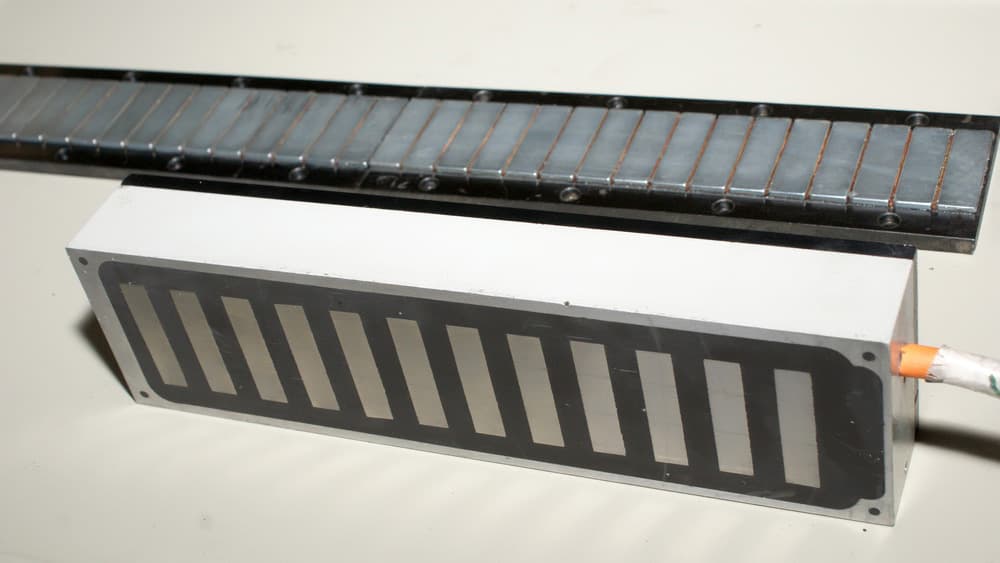
Magnetic track for 1ML and 2ML motors
| Type | B1, mm | B2, mm | K, mm | h, mm | H1, mm |
|---|---|---|---|---|---|
| 1MLW25 / 2MLW25 | 55 | 25 | 41 | 7.5 | 10.7 |
| 1MLW50 / 2MLW50 | 80 | 50 | 66 | 7.5 | 10.7 |
| 1MLW100 / 2MLW100 | 130 | 100 | 116 | 7.5 | 10.7 |
Magnetic track for 1ML and 2ML motors — dimension drawing
Technology
Direct drive
In a direct-drive system, the load is moved directly by the linear motor, with no intermediate transmission — no gearbox, belt, or lead screw. This removes backlash and transmission wear, improving positioning accuracy and dynamic response compared with a traditional rotary drive.
Areas of application
- —CNC machining, laser cutting, EDMWide-range, high-response electric drives and linear feed mechanisms of CNC metal-cutting machines
- —Semiconductor and PCB assembly equipmentAutomatic micro-wire welding equipmentPCB drilling machinesElectromechanical assembly equipmentCutting of silicon, glass and ceramic wafers
- —Sorting and conveyor systems
- —Medical micromanipulators, lab and microscopy equipment
Advantages of direct drive
- 01
Precision
High positioning accuracy, highly uniform travel and a rigid drive.
- 02
Dynamics
High acceleration and high top speeds.
- 03
Flexibility
Programmable control and easy changeover; multi-carriage and multi-axis systems; easy mounting and set-up.
- 04
Reliability
No wear and consistent accuracy over the whole service life; low noise and vibration; few components.
- 05
Compactness
Small dimensions and easy integration into existing designs.
- 06
Maintenance-free
No routine maintenance and a high degree of protection.
Operating principle
A direct drive is an electric machine that converts electromagnetic energy directly into linear or rotary motion. By controlling the magnetic interaction between the field of the moving element and that of the stationary element, the moving element can follow a path of almost any complexity.
Direct-drive systems are divided into linear and rotary motors (platforms). In a classic linear motor, an armature fed from an AC source travels above a stator made of a steel plate and permanent magnets — the so-called magnetic track — through the interaction of the alternating field of the armature with the static field of the stator.
A linear drive consists of a linear position sensor, linear guides and an AC linear motor. Force and motion are transmitted to the load without a gearbox, so no couplings, shafts or other mechanical transmission parts are needed — a clear advantage in applications that demand high dynamics and motion accuracy.
Stone processing
"Sculptor S2000" CNC milling machine for stone processing
An in-house-designed machine for artistic stone processing: high-quality 3D milling and engraving of natural and artificial stone, and — via its rotary axis — machining of bodies of revolution: oval, round and spherical pieces. Beyond stone, it also processes wood, composite materials, non-ferrous metal, acrylic glass and model plastic.
The machine's design is documented under patent No. 458Ս.
Patent documentPDFTechnical specifications
- Work table
- 1100 × 2000 mm
- Machining area X × Y
- 1000 × 1800 mm
- Z-axis travel
- 170 mm
- Linear guides
- Schneeberger (Germany)
- Spindle
- Colombo (Italy), 2.2 kW, up to 40,000 rpm, liquid-cooled
- Tooling
- ER20 collet, Ø 3–12 mm
- Feed rate
- 0–25 m/min
- Positioning accuracy / repeatability
- 60 / 20 µm
- Resolution
- 2 µm
- Installed power
- 10 kW, 380 V / 50 Hz
- Overall dimensions
- 2440 × 1848 × 1700 mm
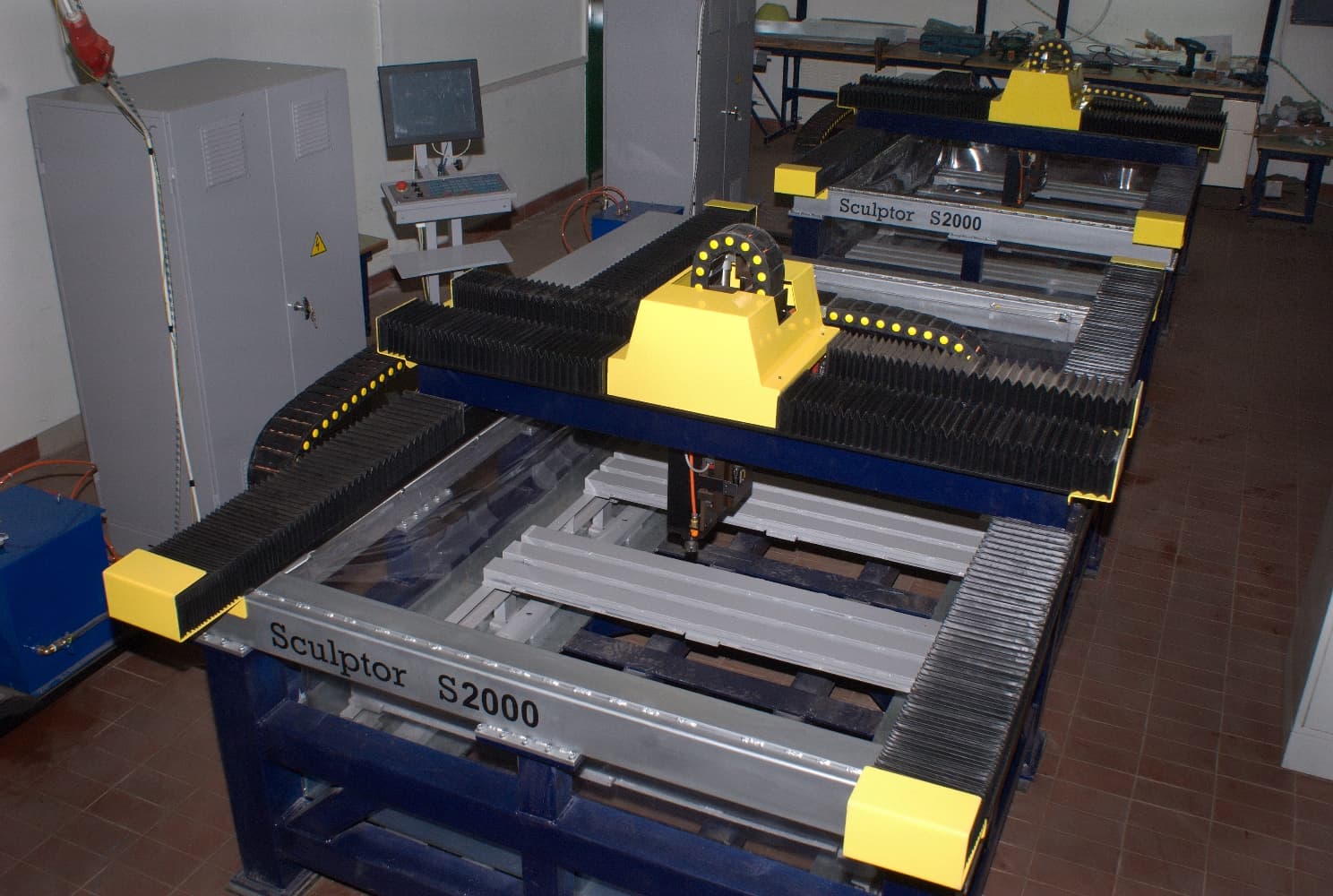
"Sculptor S2000" on the company's production floor
The machine and sample works
Photographs from the company archive.
From the company's product archive
Metal furniture
Cabinets, shelving, vault and archive storage systems, and furniture for medical and telecom facilities.
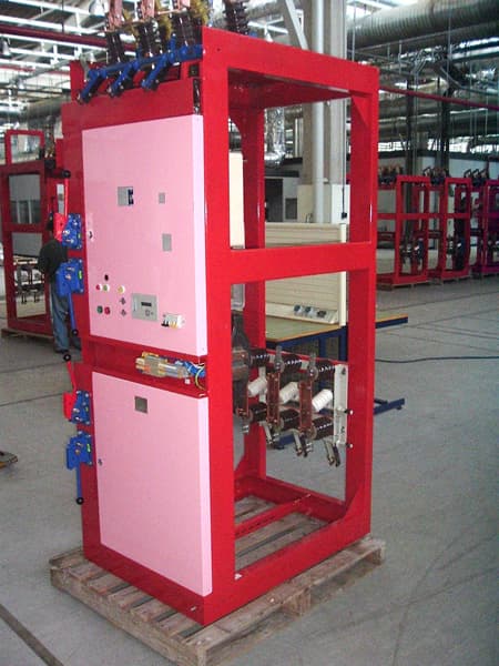
PDFSwitchgear cabinets (KSO/KRU)
Equipment for 6–10 kV three-phase power distribution, including vacuum circuit breakers.
PDFRoad signs and information boards
Manufacture of road signs and information boards.
Need a custom solution?
RAO Mars's engineering team designs equipment and electronics to the customer's own technical specification.